|
Welcome
To My Kleinfunksprecher d “Dorette”
Radio Page Two.
As I have had to do a lot of research for this
radio, I have had to spread the information out over two pages.
Radio
Unit Assembly
20.
 21. 21.
 22. 22.
 23. 23.
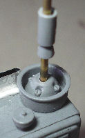
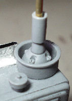
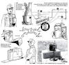
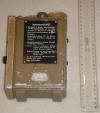
The pictures above show the various stages I have
had to do to get the radio units ready for painting, Picture
20. shows how I have drilled out the hole in
the radio unit for the aerial. I have also in Pictures
21. &
22. gently drilled out the aerial mount, so that I can fit the brass
wire through it and into the radio unit. In Picture 23.
I have drilled out the connection points for the wire that links the two units
together, it also shows the wire that I
used from the kit to connect them. Note: The
wire had to have both ends of the plastic stripped back to expose the wire, this
was then tightly wound so that it fits into the drilled holes.
Wiring Connections
24.  25. 25.
 26. 26.
 27. 27.
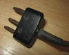
The kit comes with a pair of Dragon headphones and
a throat microphone, plus a pair of resin connectors as shown in Picture
24. I found the resin parts are not detailed
enough for me to cut off and adapt to fit. As I would also have to cut some pins
down to make the connectors, which would have to be fitted into drilled holes.
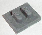
So I have used the Dragon pieces but I
found that the connection for the throat microphone in Picture
25. fits onto the radio unit ok. But the
headphone connection does not line up with the holes I drilled out. So in
Picture 26. I have cut off the two prong
connector and fitted an extra three prong one from another spare set I have. I
have also cut the centre prong off so that the new connector can now fit into
the radio unit. Picture 27. shows the
headsets with the painted end connectors.
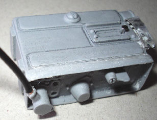
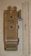
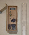
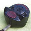
Painting The Radio
28.
 29. 29. 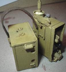 30. 30.
As mentioned earlier, I first washed the resin parts first in soapy water to remove any mould release agent, I then left the
parts to dry. Then by looking at the kit instructions I have chosen to paint the radio Dunklegelb, and on a paint conversion chart I have found that the
equivalent colour is - Tamiya XF -
60. Picture 28. is the painted radio, In
Picture 29.
I gave both of the units a
wash over with some heavily thinned down Brown acrylic paint, which I dabbed
off with a tissue to leave the dark paint in the recesses and edges. Once that
was dry I then mixed up some of the
Dunklegelb and some White
paint, to get a
slightly lighter colour which I then
Drybrushed over the radio units to add highlights.
Picture 30. is
of the radio units after I have given it a drybrush with some Gunmetal & Sand
Weathering Powders, to add both highlights and to dull down the overall look.
Radio
Unit & Battery Box Fitted Together
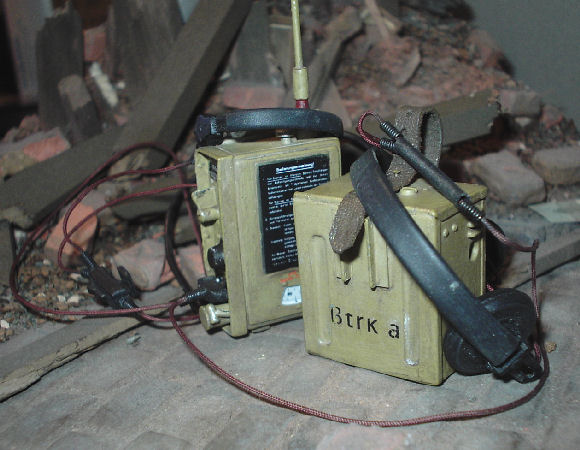
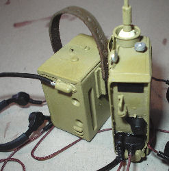
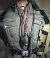
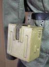
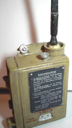
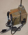
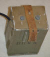
 I read a post on the Sixth Army Forum by
Heersbergfuhrer, where he has mentioned about a book
"Wireless for Wehrmacht in Detail" from WWP. And how the radio unit and the battery
box can be fitted together, to be held in one hand with the leather strap. And I
found out that with resin radio and battery box has such crisp detail, that they can
indeed be clipped together as shown in the picture on the right. I read a post on the Sixth Army Forum by
Heersbergfuhrer, where he has mentioned about a book
"Wireless for Wehrmacht in Detail" from WWP. And how the radio unit and the battery
box can be fitted together, to be held in one hand with the leather strap. And I
found out that with resin radio and battery box has such crisp detail, that they can
indeed be clipped together as shown in the picture on the right.
Additional information about how the radio was used
is in italics below by Sixty Driver:
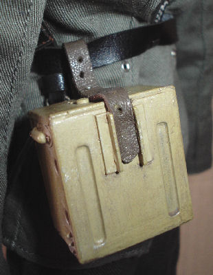
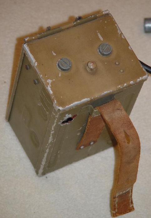
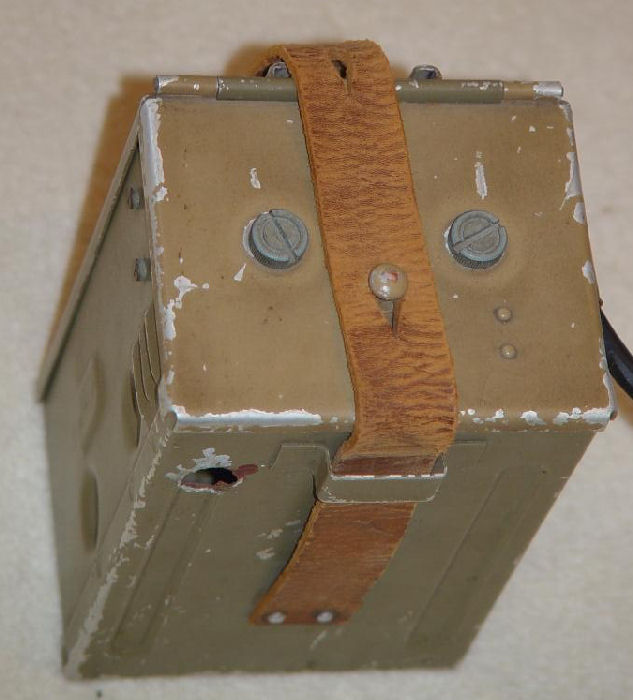
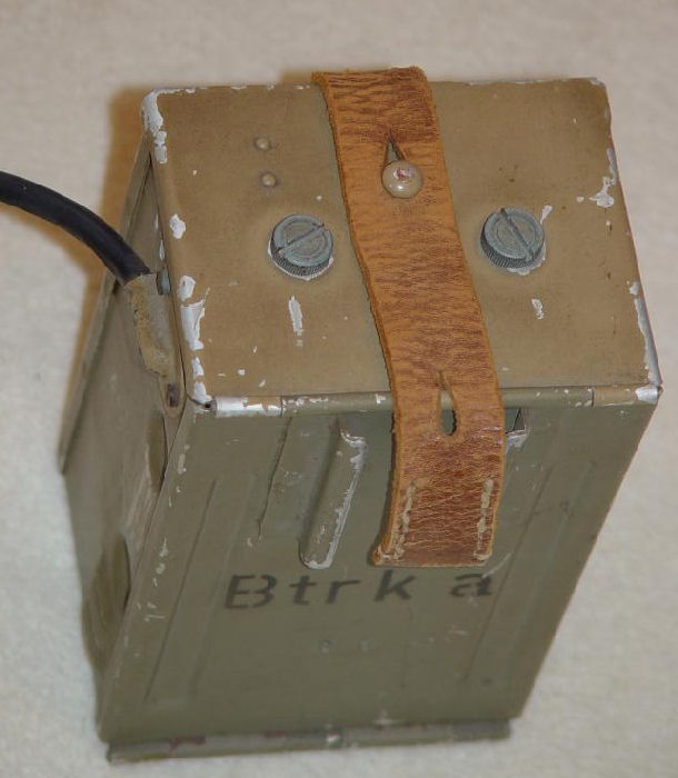
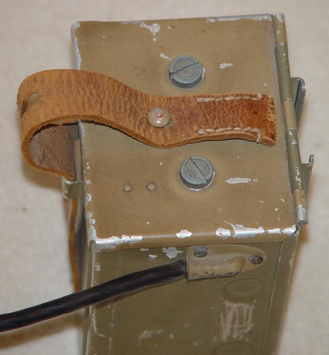
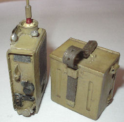
This battery box was worn on the belt. The
leather strap on the battery box was adjustable so that the set could be:
1. Radio attached to Y strap, battery box worn on belt. In this variation the
leather strap was secured to a stud on the top of the battery box and the belt
was slid between the battery box side and the leather strap.
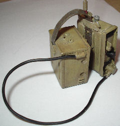
2. Radio and battery box connected. There is a slide in bayonet type of mount on
the radio and battery box to connect them. The clamp used on the Y strap was
attached to the leather strap on the battery box, the leather strap could then
be allowed slack to form a convenient carry handle for both units.
In any event for reference purposes only 1 end
of the leather strap on the battery box was actually permanently attached to the
box. The other end was loose so the radio could be configured several ways as
previously mentioned.
31.
 32.
32.
 33.
33.
 34.
34.
 35.
35.
 36. 36.

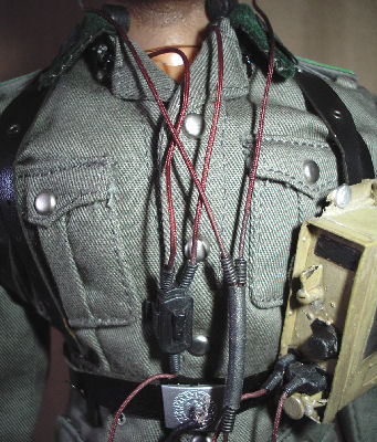
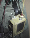
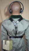
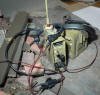
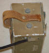
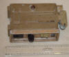
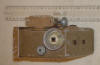
Pictures 31. &
32. shows how I have test fitted the radio units
to both the 'Y' strap and the belt on a figure, as described in 1.
above. The leather strap is passed through the metal part in Picture
33. representing the clamp,
and then fastened in place with the pin. The design of the pin in the back of
the radio unit is very good, as it does help to support the weight of the resin
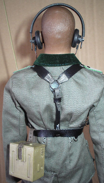
part. The same goes for the battery unit on the belt in Pictures
34. 35 & 36.
as there is a bit of weight to support with this part.
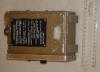
37.
 38. 38. 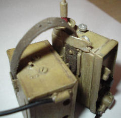
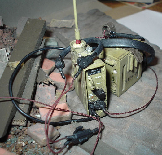
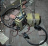
In Pictures 37.
& 38. I have loosely assembled the radio units
together as described in 2. above, and again the design of the
pins does help a lot, as they are strong enough to hold the units together. Plus
with the well designed rails on the back of each unit, they slot together easily
plus they also allow the end of the leather strap to be held in place as well.
Finished
Radio &
Decals
Important Notes: Be very careful with the decals once
you have the Micro Set on them, as I found that they can be easily damaged, as I
scratched the battery decal by accident.
They also need a coat of Matt Varnish such as
Microscale Matt Flat on them once they have dried, as this helps to
stop the decals being damaged if you handle the radio model.
39.
 40.
40.  41.
41.
 42.
42.
 43.
43.
 44.
44.
 45.
45.
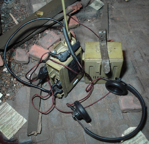
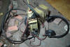
To finish the model I have had to fit the decals
to each unit, the end result is very good. But to cut them out and apply them I
have had to use a magnifying glass, especially with the White decals as I found
them almost impossible to see once I had cut them out. I also found that I had
to use some Microscale Micro Set to keep the decals in place, because as they
dried on the Matt paint they started to lift off.
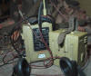
Pictures 39. to 45.
above show what the radio now looks like and are of the finished radio unit that I have placed on the base I used for my Carry kitbash, the purpose of
this is to try to get a more realistic setting for the radio.
My Opinion Of The Kit
Overall I am very impressed with this model as it has a lot of detail included,
plus the instructions are well laid out and explain the steps easily. The only
problems I did find is that the kit is made from resin, so there is a fair bit
of trimming and sanding to get the parts to fit. Which made me think, as it has
been a few years since I have used any resin parts on my models. I also had to
get a lot of reference pictures myself, to see what the real radio looked like.
But then again that is one part of the hobby that I enjoy doing, so I hope that
these pages can be of help to my fellow modellers.
 My
update of the kit My
update of the kit
I have just had some very good information about
this radio supplied to me by Funksammler in italics as below:
A few remarks if you want to get it 100% correct:
The antenna does not have a red rainguard (this is actually the antenna for the
Feldfu.b1), but is unpainted. The Dorette antenna is significantly longer (1.20
meter) than the Feldfu.b1 antenna (0,72 meter). The antenna is actually made of
strips (a bit like a tape measure) rather than a round rod.
The Dorette was typically used with a Dfh.f headset, not really with the Dfh.b
"panzer" headphones.
The leather strap sits stretches tightly around the box when worn on the belt,
the box would hang higher on the belt in reality.
In your text you mention the Dorette could also be found in black; this is
incorrect, early production Dorettes were painted dark grey.
Also consider that the Dorette was only introduced right at the end of the war,
so ideally it is displayed on a very late war uniform.
Also note that the battery box you are showing in pics 15 and 16 is a replica
and is not 100% correct.
Another issue I picked up on your Torn.Fu.d2 page: the Torn.Fu.d2 did not use a
cross on top of the antenna, the Torn.Fu.d2 is a VHF set and has a straight rod
antenna of about 2m long. The cross antenna was used with the lower frequency
sets like the Torn.Fu.b1
46.  47. 47. 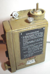 48. 48.
 49. 49. 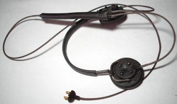
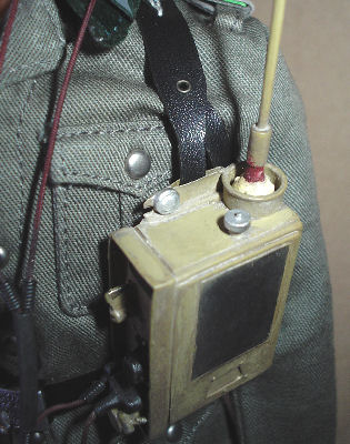
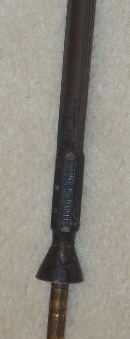
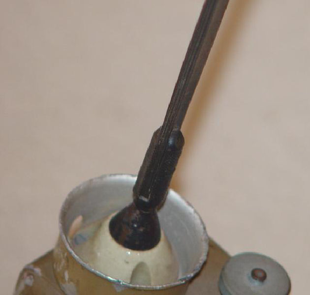
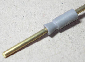
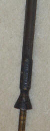
New Aerial
Based on the new information above, in Picture
46. I have made a new aerial as I broke the
resin part while I was converting it to accept the new aerial blade. The new
aerial holder is made out of plastic
sprue and I used plastic strip for the aerial blade which has been made 190.00
 millimetres
long, which is almost the scale length in 1/6th scale converted down from a 1:1
measurement of 1.20 metres. The width of it is based on the diameter of the
holder that fits into the top of the radio,
as shown in Picture 47. I have also sanded the length of the aerial, so that it is
slightly thicker at the base and
thinner at the top. Picture 47. also
shows how I have used part of the original aerial as a peg, so that I can push
fit the new aerial in place. Picture 48. is
the painted aerial in place. millimetres
long, which is almost the scale length in 1/6th scale converted down from a 1:1
measurement of 1.20 metres. The width of it is based on the diameter of the
holder that fits into the top of the radio,
as shown in Picture 47. I have also sanded the length of the aerial, so that it is
slightly thicker at the base and
thinner at the top. Picture 47. also
shows how I have used part of the original aerial as a peg, so that I can push
fit the new aerial in place. Picture 48. is
the painted aerial in place.
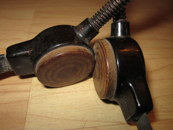
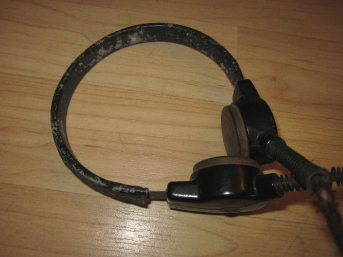
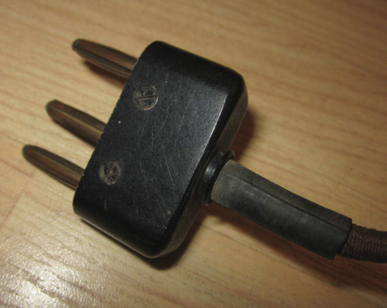
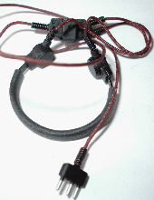
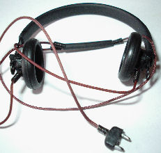
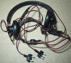
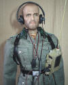
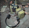
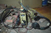
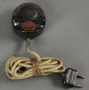
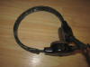
New Headphones
Picture 49. is
of the different headphones that I obtained based on the information above, and these one's
came from the Hermann Stahlschmidt figure and I believe they are the
Dfh.f headset as mentioned
by Funksammler
above. I have also had to alter the plug that fits into the radio, because the
pins are too close together.
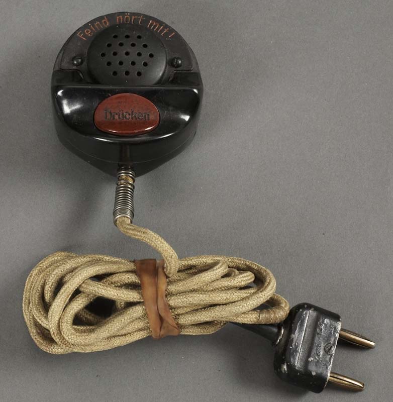
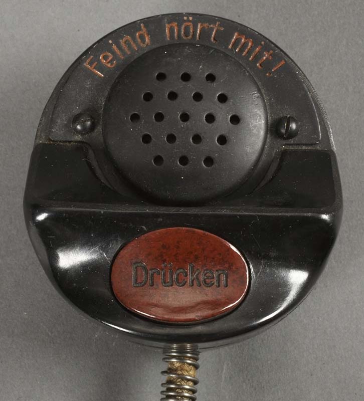
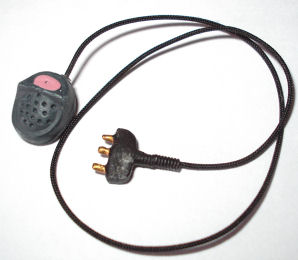
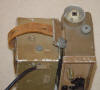
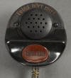
Microphone
The Dragon radio set kit comes with a throat
microphone, but I wanted to use a hand held microphone instead, As I found out
by trial and error that the resin hand is perfect for holding the microphone. So I used the
spare one I had from the Dragon Torn d2 radio kit, as shown on the right, I
have had to again adapt the plug to fit this Dorette radio.
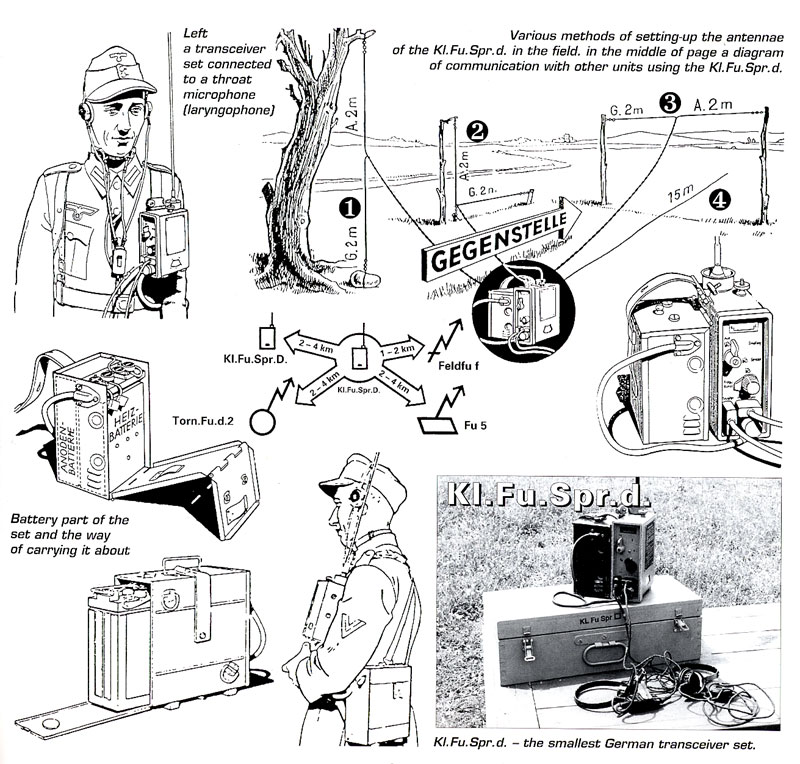
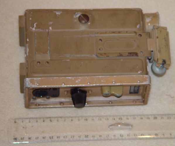
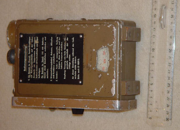
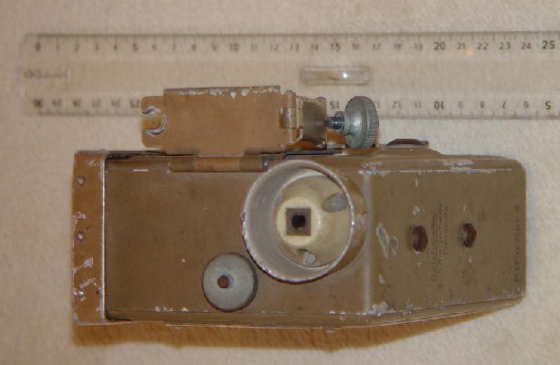
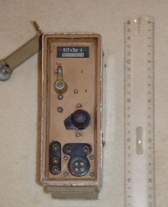
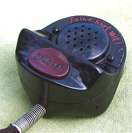
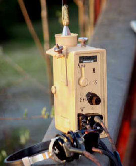
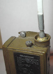
More reference pictures of the
radio and equipment.


Many thanks again to
Funksammler for his kind permission to use the above images and
for all of his help.
|