|
Welcome
To My Frank Laird Parachute Page.
DML Laird Parachute Lock Repair
Mae West Vest Update
DiD Lock Instructions
DML Parachute Assembly Instructions
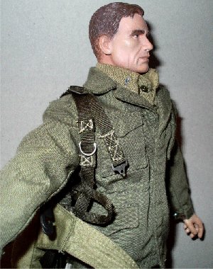
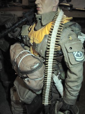
This is how I fitted the Dragon Frank Laird parachute
to my figure, I made this page after I could not find out anywhere any information on how it is worn. So hopefully this information may help someone
with their models. What confused me about the assembly of this parachute, was that I thought that it fitted the same as the Jeb one. But this is a totally
different parachute, with how it is worn. Because this parachute is put on by placing the arms through the loops, and then done up with the centre lock, not
placed over the head.
Note:
This tutorial also works with the
Ricky Foster &
Major Richard parachutes from DiD.
DML Laird Parachute Lock Repair
This section came about after I had bought the
Soldat 3 DML figure, and I tried to fit the centre lock for the parachute
together. As I had put a lot of the equipment on the figure under the oversmock,
I found that the little pips inside the parachute centre lock would not hold the
strap ends in place. Also as I had tried to tighten up the top part of the lock,
the metal screw tore out the thread inside the lower part.
To say this annoyed me is an understatement, as I now had an expensive model
that I could not use the parachute with. As the lock would not hold the straps
in place, even if I tried to use it off the figure. So after leaving the figure
for a few days, I decided to have a look at altering the base of the lock, so
that it could hold the parachute end straps in place.
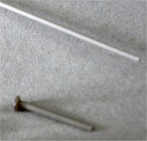
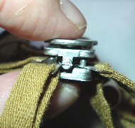
What I had to do was firstly cut off the little
pips, and then drill 4 small holes in their place. I the got some plastic rod I
had and cut off a small length of it to make the four pegs as shown below. Once
I had these I applied some heat to one end of the rod with a lighter, and when
it was soft I pushed it onto my workbench. This gave me a flattened end as shown
on the right, which I did for all four of the pegs.
Update: To make the plastic
pegs I used some plastic sprue which I stretched over a flame. This is explained
better with my Lift Dots
Repair page.
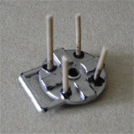
One they had cooled down, I then pushed them carefully through the holes I had
made in the bottom part of the parachute lock, as shown on the right.
I then pushed the peg back through a little bit, and placed some superglue on
the flattened ends, and pushed the end back against the lock to dry.
Again I did this for all four of the pegs, so that they are set in position to
hold the parachute ends in place.
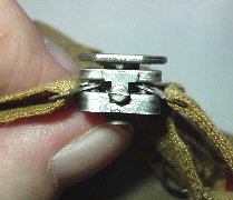
When I was certain that the pegs and glue had dried, I cut them down so that I
could still close the top part of the lock onto the bottom half.
Note:
This is shown
in the picture below left, be careful cutting them down to size. Because if you
go too far down, you will not be able get it to hold the strap in place. The
second picture below centre shows the parachute end straps placed onto the pegs,
to test that the straps fit onto the pegs. The final picture below right shows
the top screwed onto the bottom half of the lock, trapping the strap ends in
place.
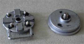
 This picture right shows the reverse of the
assembled lock, with the flattened ends of the pegs glued in place. I am going
to sand this down a bit, so the lock sits flatter against the uniform. This picture right shows the reverse of the
assembled lock, with the flattened ends of the pegs glued in place. I am going
to sand this down a bit, so the lock sits flatter against the uniform.
Note:
But be
careful doing this, as it can weaken the pegs if they are sanded down too much.
I have had to do this to two of my DML parachutes now (Soldat 3 and Frank
Laird), and I am not very impressed with the way that these are made.
Considering that these locks are made in metal by bbi. I have both the German
and RAF parachutes, and I have never had this problem with those parts. So I
cannot understand why DML cannot make them the same way?
Note: Be careful of handling
the outer or front part of the lock too much, as the wording can be rubbed off.
DiD Lock Instructions
1.
 2. 2.
 3. 3.
 4. 4.
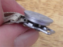
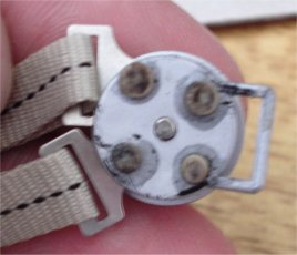
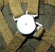
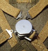
This is the centre lock for the DiD parachutes which I think are
made from metal and spring loaded, plus just like the bbi parachute locks they
are a lot stronger than the plastic Dragon locks as shown above. Picture
1. shows the lock and the straps assembled
in place, Picture 2. shows how by gently
squeezing it together and by turning the top part of the lock to the left, the
straps can now be removed from the centre lock.
Picture 3. shows the undone
lock from the side, with the metal ends of the straps hooked over the pins
inside the centre lock. In picture 4. the
lock has been squeezed together, and the top part has been turned to the right
to lock the straps in place.
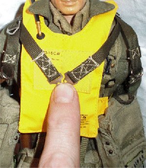
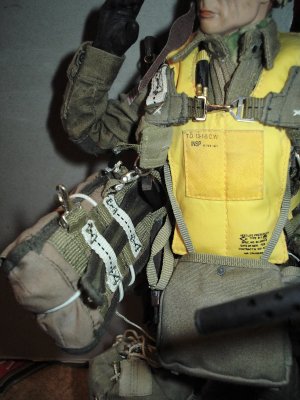
Mae West Vest Update
Note: If you are using a Mae
West vest with the paratrooper figure, this goes on before the parachute and the
parachute harness straps go over the top of the Mae West vest.
I apologise for not adding this section before, but I was
informed incorrectly that the vest went over the parachute. And after it was
explained to me how the equipment was worn, I have had to change my figure
around. So that the Mae West vest is now under the parachute harness.
Plus I have also learnt from fellow modellers, that the straps
did indeed go over the vest. Because thinking of it after it had been explained
to me, you would want to ditch the rapidly waterlogging parachute as fast as you
can before it dragged you underwater. And at the same time you would also have
to try to inflate the vest as
well to try to keep you afloat, plus try to ditch all the heavy equipment that
you were carrying.
DML Parachute Assembly Instructions
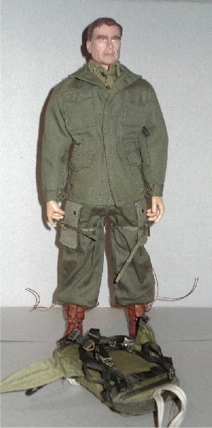 
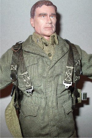
The pictures above the first stages of the
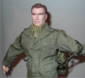
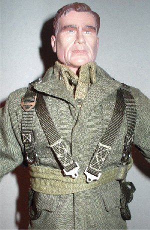
assembly of the parachute on to the figure. Step 1
is the figure without the parachute, the Step 2
shows the arm placed through the right hand side loop, so it is just hanging on
the shoulder, the Step 3 shows the other arm
placed through the other loop.
Reserve Parachute Attachment Update
After adding the updates for the Jeb and Corbin
parachutes, I was wondering about an update for this figure's parachute.
Although with this figure I have not shown a reserve parachute fitted, I did
actually use one but I had not yet got around to updating these pictures.
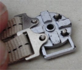
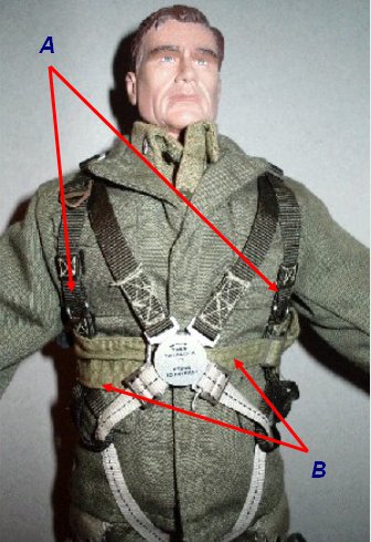
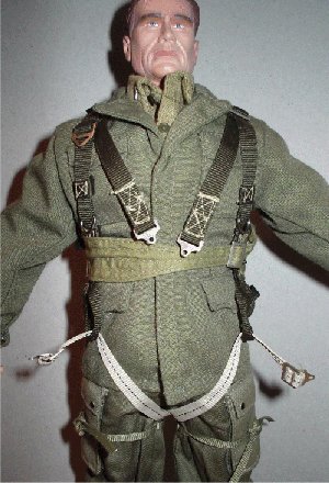
The reserve parachute clips fit the same as the
other chutes onto the harness loops as shown on the right
A, and the belly band goes through the back of the reserve
parachute to hold it in place. Then it goes across as shown in the rest of the
tutorial, and then connects up with the buckle on the other side. In the same picture
I have marked B, this is to show that the
rear reserve parachute loops have to go either side of the centre lock. The information as supplied in this topic on the
Sixth Army Forum about how to connect a reserve parachute to a harness -
Hooking up
a parachute Made me look at the errors in my tutorial here, and it was in
that topic, that I got to thinking about this type of parachute with a reserve
fitted to it.
A very helpful piece of information in that post
came from USMCPrice, and I have copied it below. As I feel it explains
this much better than I ever could, about the reasons for connecting the reserve
chute to the belly band.
The pictures above show the belly band going through the spare
parachute loops and what it looks like finished.
He also explained in detail
about why the reserve chute is connected to the belly band.
I've never jumped a T5 but I have jumped a T7,
T10 and MC1-1 and they are all rigged with the belly band through loops on the
back of the reserve. I am sure the T5 would have had to be rigged this way also
because the two hooks connecting the reserve to the main parachute harness would
not be sufficiently strong to support the weight of the jumper and his
equipment. When the reserve is deployed it suspends the jumper from his abdomen,
belly up with his body parallel to the deck, without the belly band that's a lot
of weight and force placed upon two small hooks.
The pictures above show
Step 4, this is where the parachute has been pulled up onto the
shoulders, so the whole parachute hangs down the back including the seat strap.
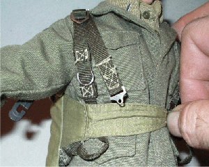
Step 5 shows the belly band pulled around so
that it traps the straps underneath it. Note:
make sure the loop hangs down, as the leg straps go through this.
Step 6 shows the belly band brought over and
threaded through the buckle, again trapping the straps underneath on this side.
Note: See the update about the fitting of
the reserve chute above, as the strap has to go through the loops on the back of
the reserve.
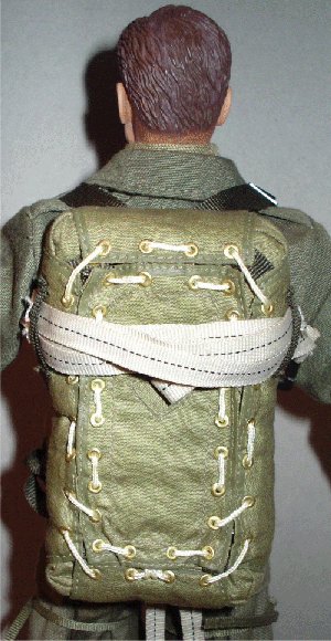

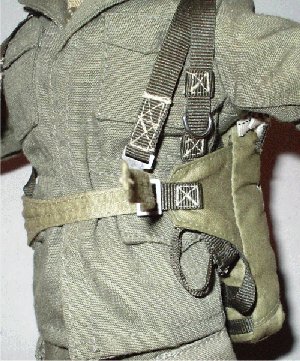
 Step
7 shows the belly band done up and the top pair of straps brought
forward, the next picture just shows the parachute as it looks from behind.
Step 8 shows the rear leg straps brought
through between the legs, then threaded through the loops I mentioned earlier.
Step 9 shows the straps connected and
adjusted to fit on the shoulders, with that the parachute is fitted to the
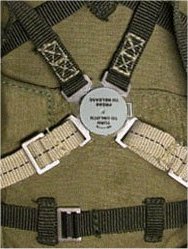
figure. The picture right, shows a close up of the lock assembly, plus the
buckle for the straps adjustment. Step
7 shows the belly band done up and the top pair of straps brought
forward, the next picture just shows the parachute as it looks from behind.
Step 8 shows the rear leg straps brought
through between the legs, then threaded through the loops I mentioned earlier.
Step 9 shows the straps connected and
adjusted to fit on the shoulders, with that the parachute is fitted to the
figure. The picture right, shows a close up of the lock assembly, plus the
buckle for the straps adjustment.
Note: I had a
problem with this parachute and the centre lock as made by DML, because when I
assembled my British para figure, it uses the same plastic lock for the straps.
And as soon as you put any of the straps under pressure, they keep coming
undone. Which will gradually wear out the little pips that are supposed to hold
the metal ends in place. Plus the top part of the lock with the metal thread,
will also eventually strip out the plastic thread in the hole on the bottom half
of the lock. Which will leave you the only choices of either glueing the parts
together, or doing as I did with my parachute lock at the top of the page.
Parachute Usage and Fitting
Update
I have just received the following information by
e-mail from Joshua about the WW2 US T-5 and
T-7 parachute and harness, and because I feel that it is so informative. I have
posted it here on this page to hopefully help my fellow modellers. Plus, I would
like to thank Joshua for taking the time to share this detailed information with
me.
I have studied the T-5/T-7 parachute for years
and just thought I would give you a little information. The belly band isn't
there to support weight. It's purpose was for keeping the reserve from flapping
around, and also worked great to secure equipment. Its attaching seams will not
hold very much weight-its sewn with the regular parachute pack thread, about 8
lb. tensile strength. The two reserve hooks/d-rings are plenty strong. They were
rated at 5000 pounds. (the original ones were the reg. harness hooks, rated at
2500, but by D-day just about all were the 5000 type).
The hooks will go 8420 pounds to the maximum
bend. That's when the hooks would bend far enough for them to come off the ring.
The rings have a much high bending strength. That means it can safely take an
opening shock of 10,000 lbs, or approx 40 opening g's (at about 40 g's your
probably dead). Even in the worst conditions - the reserve opening at 250 feet,
300 lb weight, 1.5 second inflation time, and at terminal velocity the opening
shock would only be about 2400 lbs. Normal opening shock would be in the
vicinity of 1300 lbs for the reserve, and that's probably a slightly high
number. Some troopers on combat jumps cut off the belly band to be able to shed
the harness faster.
Also, when the reserve opens, it doesn't
suspend the jumper at that much of an angle. Though he isn't suspended
vertically like when the main is open, he is still close to vertical, though it
isn't very comfortable. This is especially true when there is a heavy load of
combat equipment; it pulls the jumper slightly more vertical with all the weight
at the bottom. Hope this helps.
Note:
Realize though that the opening shock forces have so many variables, so the
numbers are not extremely accurate.
Many thanks to both
USMCPrice and
Joshua for the detailed help and information. |
