|

Welcome
To My German Ski Alterations Page.
This page is one that I have wanted to make ever
since I started making Gebirgsjager figures, and after seeing the
85th Gebirgsjager Living History Group
at the Detling show in 2011. I realised just what was missing from the standard
models of the ski's as made by Dragon.
So to give me something to do, I have finally
decided to see if I can add some more detail to the model ski's.
Some of the items that I noticed that are missing,
one is the green stripe on the top of the ski, the locking clip on the binding
for the skier's boot and the groove on the underneath of the ski. Also missing
is the piece at the tip of the ski, which has a hole in it the purpose of which
I am unsure of, as well as the thin metal edges on the underneath of the ski.
Update - I
have had some help from a fellow modeller Ludger Zikking, and he has explained
below about the hole in the front of the ski.
I can shed some light on something: you mention
your ski alteration page: "Also missing is the piece at the tip of the ski,
which has a hole in it the purpose of which I am unsure of, as well as the thin
metal edges on the underneath of the ski." Maybe I can shed some light on the
use of the hole: with alpine touring, to make progress going uphill, you use
skins, and some brands use a hole in the tip of the ski, to attach it to the
ski. You don't see it that often anymore these days, since most brands use a
steel cable for that purpose.
The pictures below are from my Detling 2011 page,
which I have used here to help explain about the ski's.
1.
 2.
2.
 3.
3.
 4.
4.
 5.
5.
 5a.
5a.
 6.
6.
 6a.
6a.
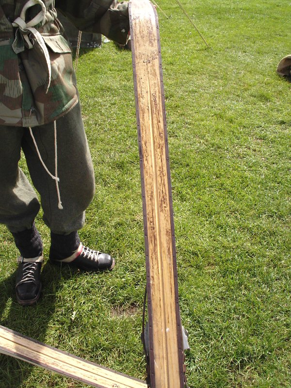
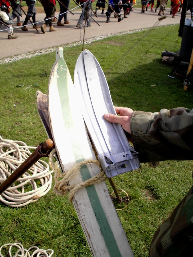
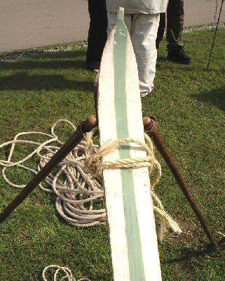
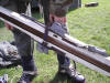
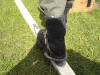
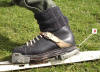
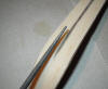
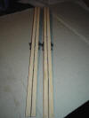
Picture 1. is
of one of the straps that are used to hold the ski's together, Picture
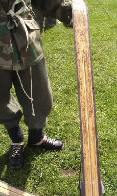
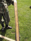
2. shows the underneath of the ski, the
metal edges are to help the skier turn as the metal strips dig into the snow.
The brown colour is due to the wax that is applied to the underneath of the ski,
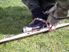
to help reduce friction and increase speed. Picture 3.
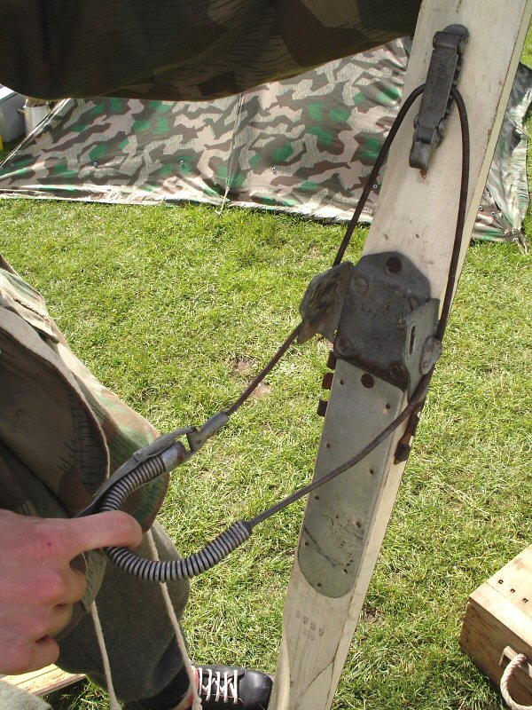
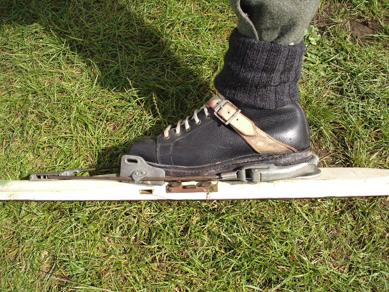
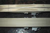
shows the bindings for the ski boot, Picture 4.
shows how the bindings are adjusted to the different sized boot for each skier.
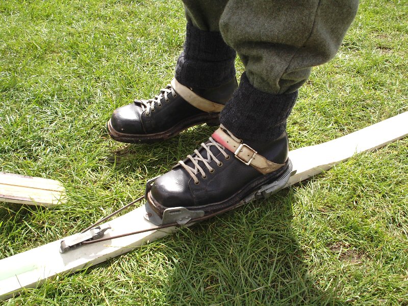
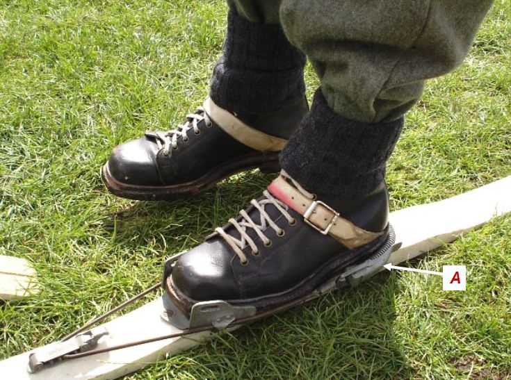
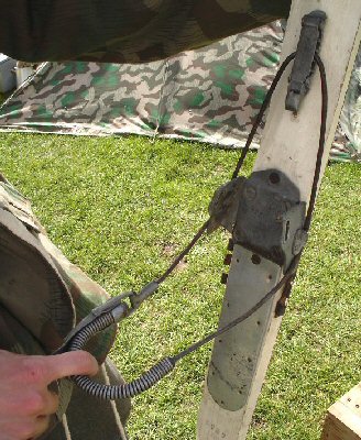
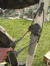
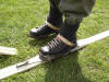
Picture 5. & 5a. (A)
shows the spring clip at the back of the binding which is used to keep the boot
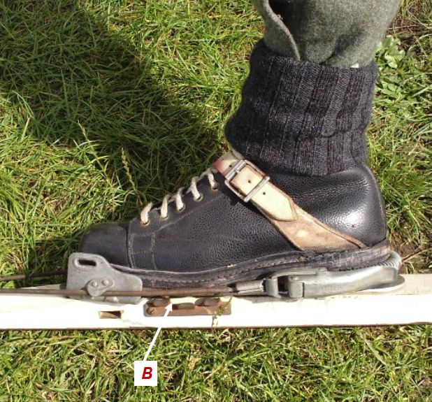
in place. Picture 6. &
6a (B).
shows the ski boot in position, with the wire for the binding not connected to
the side of the ski.
7.
 8.
8.
 9.
9.
 9a.
9a.
 10.
10.
 10a.
10a.
 11.
11.

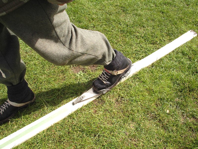
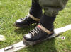
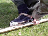
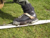
The purpose of this is that as shown in Picture
7. is that the foot can be bent and moved
further, so that the skier can 'walk' faster over the snow. Because from what I
understand of it, only the toe of the boot is fastened to the ski. Picture
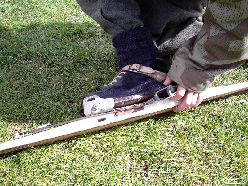
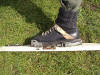
8. shows the back of the binding. With
Picture 9. & 9a.
(C)
the wire on the binding has now been placed under the clip on the
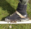
side, and in Picture 10. &
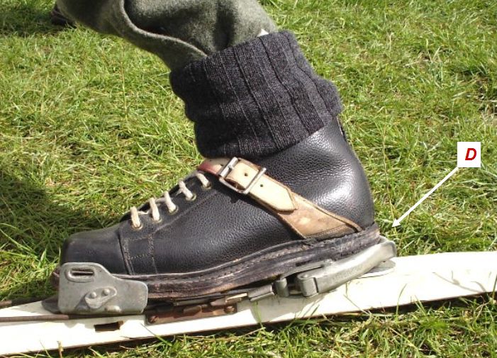
10a. (D)
there is a lot less movement of the foot and the boot is now fully
secured to the ski. In Picture 11. I was
shown an adjustable metal plate, which is used to replace the front of a ski if it gets broken.
Ski Alterations
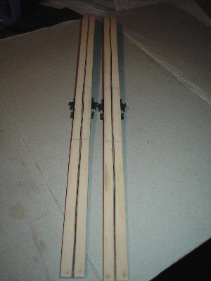
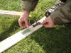
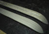
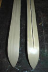
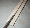
The first item that I added to ski was the centre
groove on the underneath, which I did carefully with a round needle file sanding
a central groove into the base.
9.
 10.
10.
 11.
11.
 12.
12.
 13.
13.
 14.
14.
 15.
15.
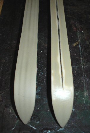
Although I did this freehand the groove is
almost straight, but looking back I should have first measured the width of
the ski, drew a line on it along the length and then used that as a guide for
the sanding with the needle file. Pictures 9
& 10 show where I started to sand the
groove, 11 & 12
show the round needle file I used, 13 shows
the length of the ski's with the groove, and 14
shows where I have sanded the middle underneath the ski to remove the moulding
line that was there. To check that I was keeping the groove straight, I used a
pencil to colour it in as I did it, and that did help to keep me the line
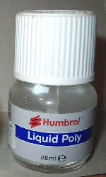
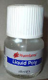
straight. Picture 15 is of the liquid model glue
that I used to on the sanded groove afterwards, this helped to make it all
smooth.
This section is continued on
Page Two
|