Welcome
To My German Torn.Fu.d2 Radio Page One.
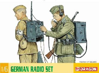
This page is about the changes I have made to the
Dragon Torn.Fu.d2 radio model kit. This
is my first kit from Dragon and I am very impressed with the crisp detail with it, although I personally did find it awkward to try to follow the instructions,
as I am used to the old type of Airfix kit with the step by step instructions. I
also found a problem with the numbers on the sprues, which I had to write over with a pencil at times to highlight the numbers.
Back
Pack Radio Unit Kit Changes
Batteries
With the radio units, one of the main items that I
discovered that are missing from the kit is the batteries. But with the very
kind help of David (Actionman) I have been able to make a pair of them for the power unit. And seeing as I wanted the unit open, these were quite a
vital part of the radio set.
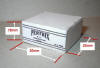
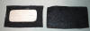
The picture on the right shows the dimensions for
one of the two batteries that I made. I first cut out a balsa wood shape, and then cut out and stuck some white card squares all around it with PVA glue, I
then used the label on the front. While it was drying I pressed hard on the edges of the card with my fingers, to make it conform to the shape of the balsa wood.
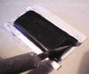
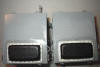
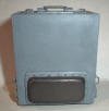
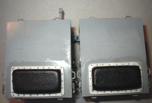
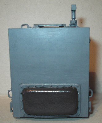
Radio Units Backpack Pads
As shown on the right, another item that is
missing from the kit is the leather pads on the back of each of the radio units.
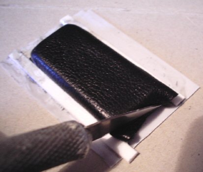
So I have had a go at replicating the pads on the
back of my radio units as shown below left, I have used some leather material
for the pad itself which is to be re-painted Brown. Making the pads and the plates that they sit on
are shown above, the first part of it was to make a balsa wood shape for the pad
as shown in Picture 1. This was then stuck
onto a square piece of leather material with some double sided tape, the
material was then cut so that the edges when folded was slightly longer than the
balsa wood.
1.
 2.
2.
 3.
3.
 4.
4.
 5.
5.
 6.
6.
 7.
7.
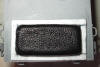
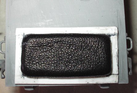
In picture 2. I have put another
piece of double sided tape onto the balsa wood, turned it over and stuck it onto
a larger square piece of plastic sheet. Also in Picture 2.
I have then cut out some plastic strip for the sides, and then glued it onto the
plastic sheet to trap the edges of the leather material in place. Picture
3. shows all of the strips glued in place,
with the leather material pressed in around the edges to make it look a tight
fit. Note: This is still the rough shape
after trimming the plastic sheet to the size of the strips. all of this will be
sanded flat and the corners of the strips will be rounded off.
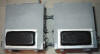
Picture 4.
shows the pair of pads placed onto the back of the radio units, to check that
they sit right. Picture 5. shows the type of
glue that I have used to make both these pads and the kit, and from my
Tools page I have the
information about them in sections 29, 30 & 31.
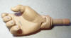
Picture 6.
These are the finished pads fixed onto the back of the radio units, and picture
7. shows the size of the rivets in a 1/6th
scale hand that I used around the edge of the pads. These were the
0.9mm
spherical rivets that I bought from
Master club UK on eBay, and I just had to add these here to get a better
detail on the model.
 Radio
Dials Alterations
Radio
Dials Alterations
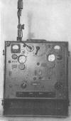
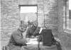
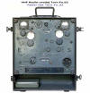
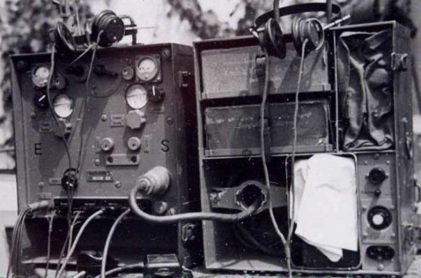
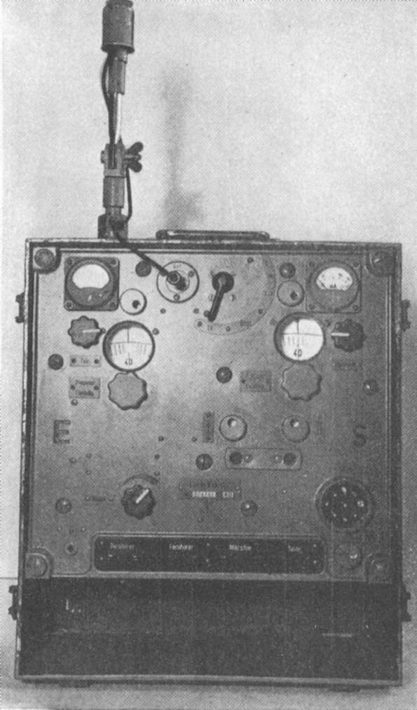
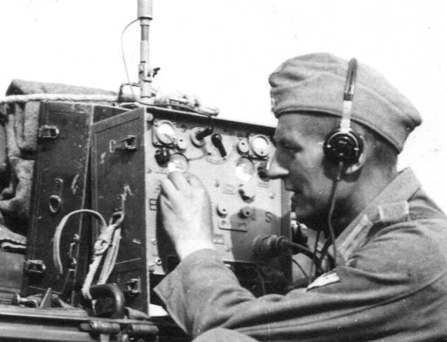
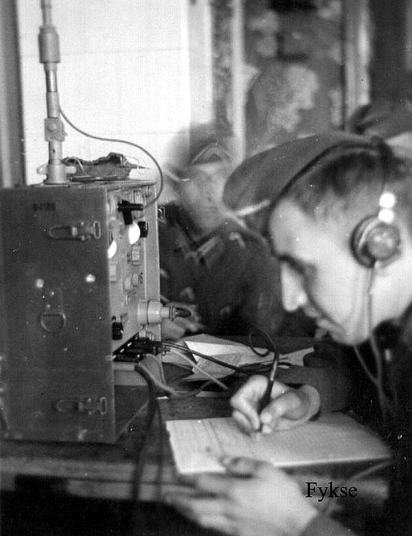
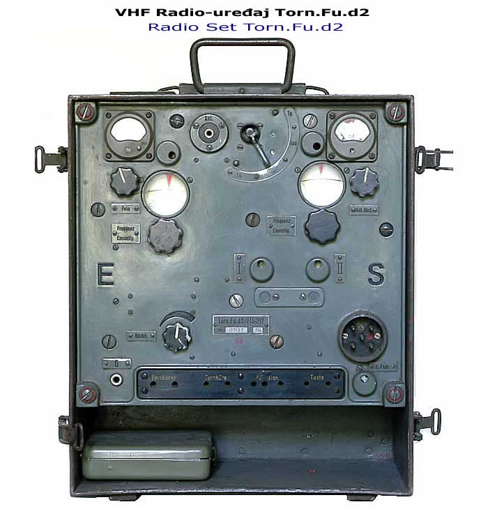
With the frequency meters dials for the radio I am
afraid that I just had to copy the work done by Sgt Shultz II, as the effect
that he got with the magnifying lenses is outstanding. And I just had to have
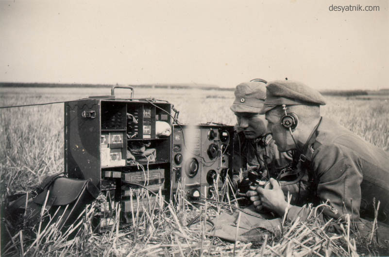
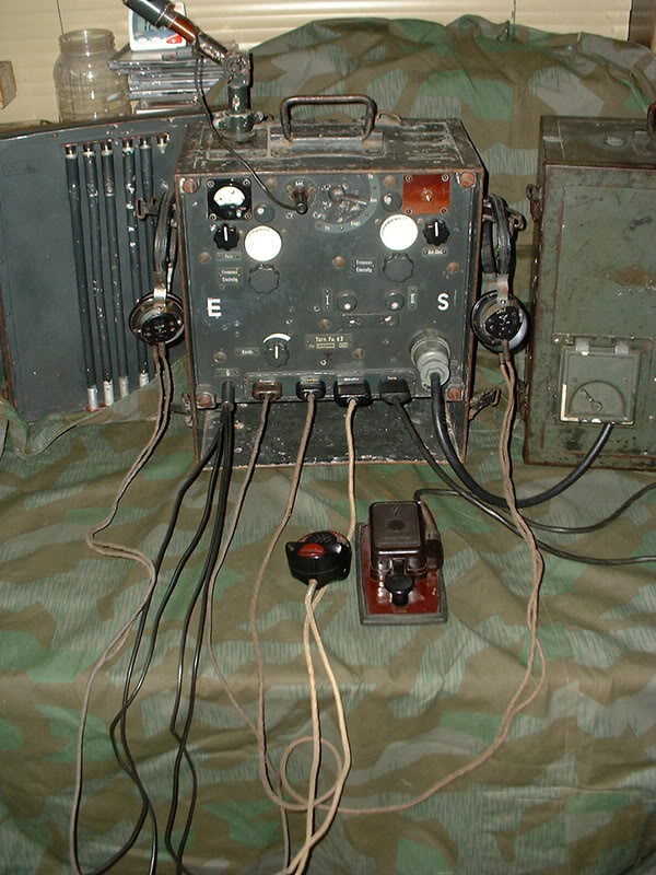
the same effect on my radio unit. The picture on the right shows a full size
radio with the lenses in place, which help to show the gauge better. The other
image on the right is of the radio unit made by Sgt Shultz II, which shows how
the lenses do make a real difference to the model.
Comment by Sgt Shultz II:
To do this mod I shaved off the lens bezels and
drilled them out with a number 4 drill. I used real magnifying lenses from a
model train hobby shop. There is no bezel on the dials but they do have glass
lenses like a magnifying glass.
I had to do a lot of searching around the internet to find the lenses for the
radio, although I did find some for sale in the USA the price for them and
shipping to me in the UK was just too expensive. But I did find some in the end
courtesy of some very kind people, who pointed me to this website -
Little Cars and this is the list for
the lenses and scale wiring - Little Cars.
8.  9.
9.
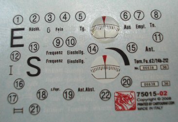
In the pictures above 8. shows how I have drilled
out the holes for the dials and also removed the raised edge that was around
them. And in picture 9. I have placed one of
the 5mm lenses on top of the frequency meters decal (14). And I feel that it really does
improve it, especially when you compare it to the plain flat decal below it.
 Shoulder
Strap Alterations
Shoulder
Strap Alterations
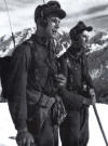
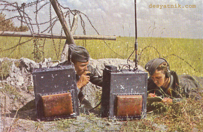
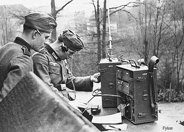
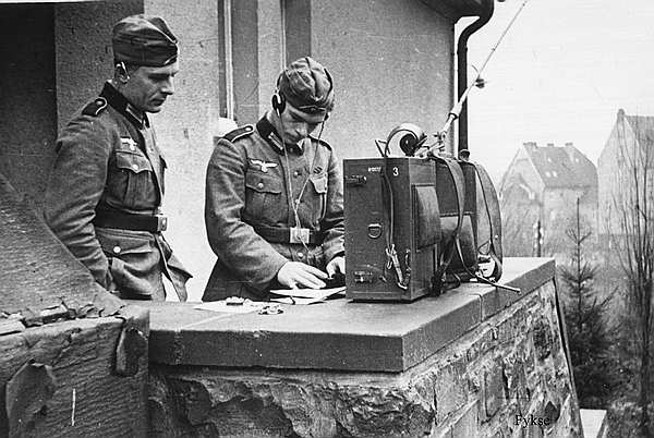
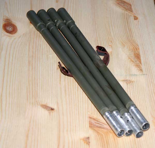
The straps that came with the kit, I personally
found them to be poorly made. As they are of a webbing type of material which
has been covered on one side with a thin strip of vinyl. So I used two pairs of
DiD 'Y' straps to replace them, based on the reference picture on
the right. But the problem was that the radios could not be fitted to the
straps, as they need a new set of auxiliary straps to be able to reach the 'D'
rings on the top of 'Y' straps.
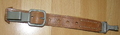
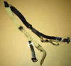
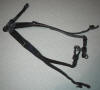
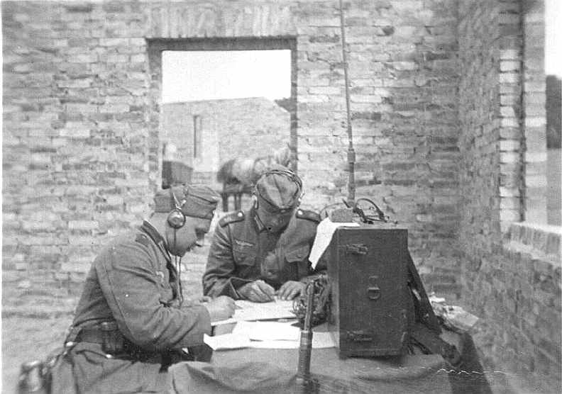
This is where a little bit of 'Modellers Licence'
comes in, as I found a picture on a forum shown below of what look like
extension straps for some kind of German back pack mounted equipment. So I have
decided to make these straps for the radio units, so that I can use the DiD 'Y' straps.
In the images below, Picture
10. is
of the 'Y' straps as they came with the kit, compared to the DiD straps in
Picture 11. which are of a better pleather type of material, also the DiD straps have the
extra 'D' rings on the top as well.
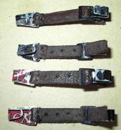
In Picture 12.
I have made some auxiliary straps to connect the radio to the 'Y' straps, these
were made with four strips of leather into which I drilled the holes for the
buckle holes. The metal connecting ends I made from some aluminium that I cut
from an empty beer can.
10.
 11.
11.
 12.
12.
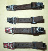
With the connecting end on the left, I folded the
aluminium in half to double the thickness, and used some super glue to stick it
together. Cut it to shape and I then drilled and enlarged some
holes and threaded the leather strip through it, I then sewed the ends
together. The other side of the strap had a thin strip of aluminium again folded
in half, glued, threaded through the buckle and bent round to keep it in place. Both ends of the connectors were bent to shape, and checked that they fitted
into both the top of the radio and the 'D' rings on the 'Y' strap. The final
part was to paint the aluminium parts with some enamel Gunmetal paint.
Assembly Of The Radio Units
9.
 10.
10.
 11.
11.
 12.
12.  13.
13.
 14.
14.
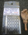
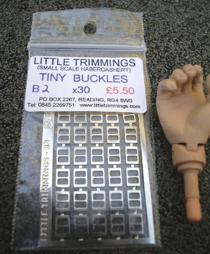
The pictures above are of the radio units as I
have assembled and also altered the parts, in Picture
9. shows the
small buckles I bought from
Little Trimmings I used the
B3 one's for the battery holders. Picture
10. is of the straps for the
batteries which are made from leather strip I have. That I got from the USA from
Rio Rondo it is listed under the title
Leather Lacing, and when I want to get some more I found a company here in the
UK, that supplies the same items
Dolls House Trims. I also added a small strap and buckle to the other power
unit, because I could not see how this unit would be fitted in real life.
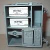
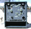
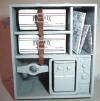
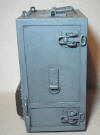
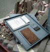
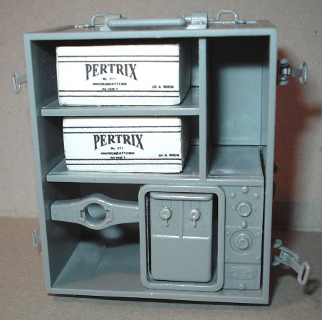
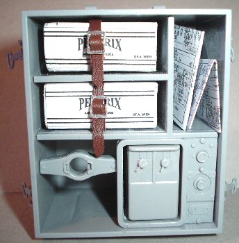
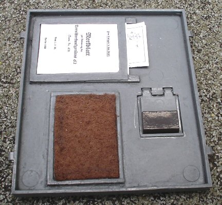
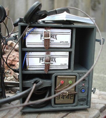
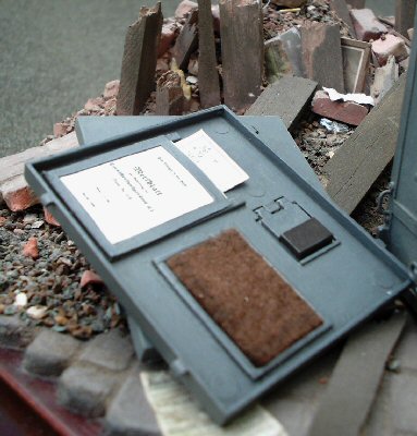
Picture 11. is of the
inside of the cover for the battery unit, and again I just had to copy the work by
Sgt Shultz II for this, as it does add more detail to the radio units with the
felt pad and the holder for the manual. The paper items I have placed in the
radio, were found here -
Circuit Diagram
and Manual Cover, these were
printed out and folded up to fill the spaces.
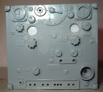
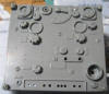
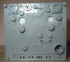
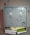
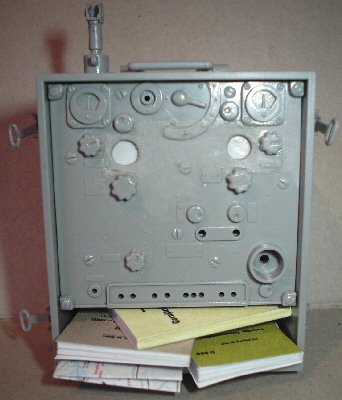
Picture 12. is
the front of the control unit as it is on the sprue. Picture 13. is of the main front part of the
radio control unit, with the dial holes drilled out and the raised edges around
them removed. The area around the holes has been gently sanded to remove the
last part of the bezel or raised edges, and I placed some thin plastic sheet
behind the holes, to support the decals and the glass lenses. Picture
14. is of the radio manual books I bought from
One Sixth Scale
King, as I wanted something to fill out the empty space in the radio.
15.
 16.
16.
 17.
17.
 18.
18.
 19.
19.
 20.
20.
 21.
21.
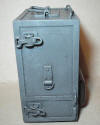
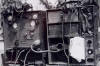
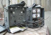
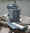
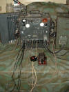
These pictures are of the assembled radio units
after I have painted them, the kit instructions say to use Model Master Color
H3240 (1723), but because I cannot find the paint here in the UK. I have had to
use Revell paint instead Staubgrau 36177, which I found by using this
paint conversion chart.
Pictures 15. 16. &
17. are of the main radio control unit, which has had the pad fitted
and the casing painted. Once this was dry, I gave both of the units a
wash over with some heavily thinned down Black acrylic paint, which I dabbed
off with a tissue to leave the dark paint in the recesses and edges. Once that
was dry I then mixed up some of the Field Grey paint and some White, to get a
slightly lighter colour which I then
Drybrushed over the radio units to add highlights.
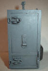
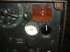
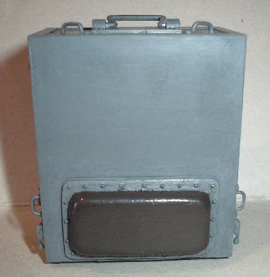
Pictures 18. &
19. are of the front control unit, this was
painted the same colour as the case, with the main dials painted a slightly
lighter shade of Field Grey. The screw heads and rivets were painted Gunmetal,
over which I wrote with a pencil to bring out some highlights.
22.
 23.
23.
 24.
24.
 25.
25.
 26.
26.
 27.
27.
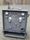
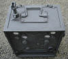
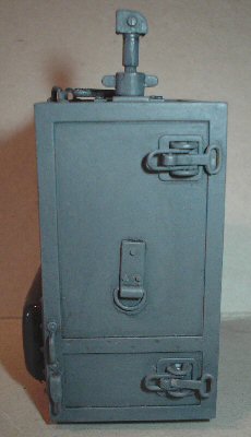
Pictures
20. 21.
& 22. are of the battery unit case, this was
given the same treatment as the control unit. I have also on both units, used a
pencil to write along all of the edges, around the mountings and clips and over
the raised details. The purpose of this is to add a slight shiny line on these
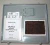
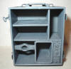
parts. Picture 23. shows the inside of the
battery case with the lower right controls still to be painted.
Picture 24. shows the felt pad held in place
with some double sided tape, also the manual and wiring diagram fitted in the
holder.
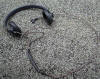
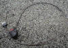
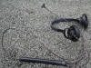
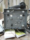
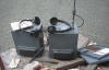
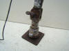
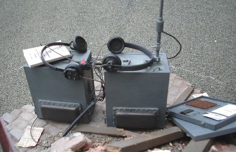
Assembly Of The Wiring, Microphone And
The Headphones
The microphone and the headphones are shown above
in the pictures 25. 26. &
27. Note:
That the headphones in picture 25. are of
another pair that I had in my spares box. The parts that came with the kit were
assembled and painted as the kit instructions say, with the wire repainted Brown
to cover up the glue stains. I then went over the wire, microphone and
headphones with some Light Sand weathering powders.
Note: Part Z9
(30mm soft air hose) for the headphones is made of a heatshrink material, and to
make it smaller for the wiring. I held it, moved it about over my cigarette
lighter, which gradually caused it to shrink thinner.
Note: Do be careful doing this as it gets hot, and it will easily
burn if it is too near a flame.
From the Aeroscale review of the kit assembly.
On the radio
box, I recommend painting and applying decals before inserting the piece into
the box as it will be easier to get the small details.
On the headphones, parts B-32 and 33 are best
placed after the cord is glued in place. The power hookup cord is not clearly
shown assembled but the two short cords are placed in the end of the long
plastic tubing, then run through a small gap in the battery compartment and
hooked to the battery box.
The black hose for the main connection between
both radio units, and the thinner hose for the aerial were both painted with
some Model Color Matt Medium paint. The purpose of this is to lose the shiny
effect it has, once dry this was given a light brush over with the Light Sand
weathering powders.
Finished Radio Units
From a post I made on the MDFC forum, I have had
the following very helpful reply from an MDFC member-
seeing the
unseeable.
28.
 29.
29.
 30.
30.
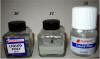
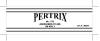
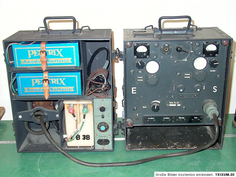
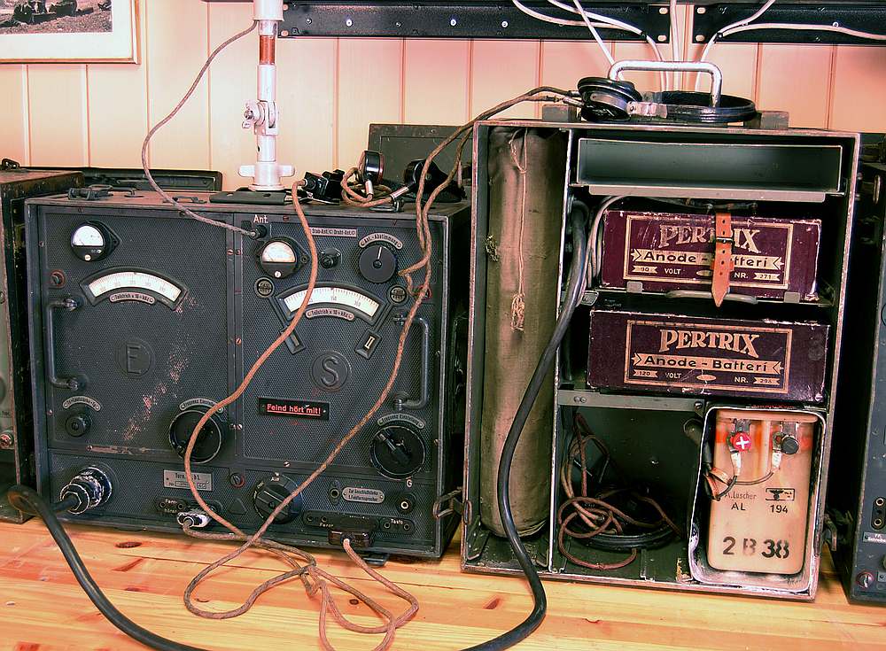
Comment by seeing the unseeable:
Nice to see that the Pertrix battery label
graphics (picture 28.) I did back
when Anton and Vaprossov were released are still making the rounds. The first
set I made were of the blue label (picture
29. you showed in one of your reference
photos, but I was told that that the black/white version was more appropriate
for the period so I worked up a set of those labels, which you've used on your
batteries. Since then, I've heard from various sources that both versions are
accurate, but I'm no expert. Also, I recently came across another label
variation I hadn't seen before in an eBay photo auction; I wish I could make the
data out, but the photo is just too indistinct, I'm afraid.
28.
 29.
29.  30.
30.
 31.
31.
 32.
32.
 33.
33.
 34.
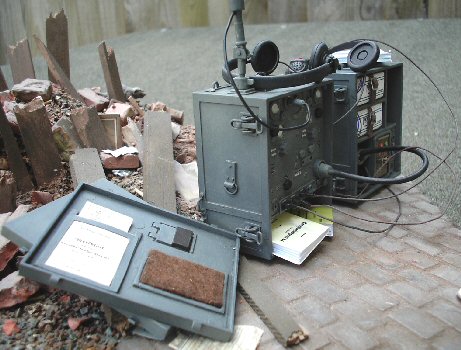
34.
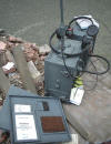
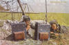
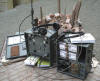
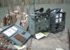
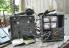
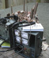
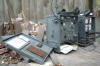
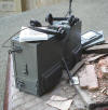
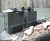
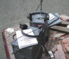
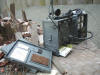
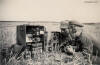
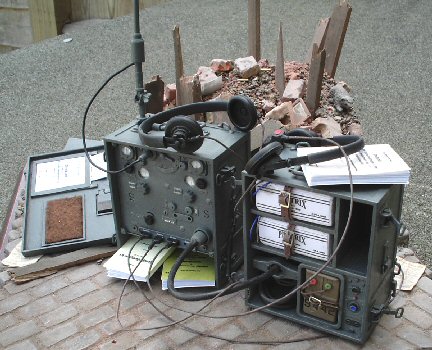
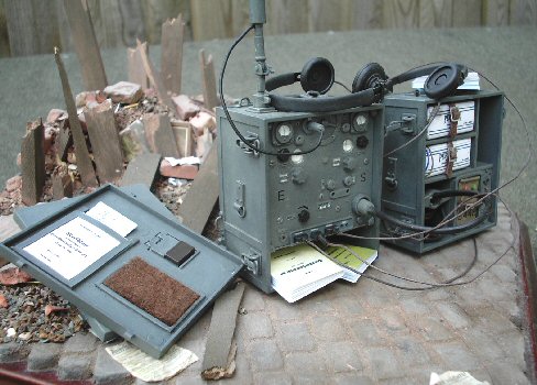
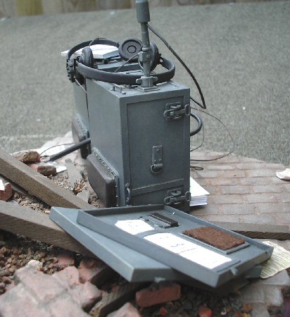
These various pictures above and bellow are of the
finished radio unit that I have placed on the base I used for my
Carry kitbash, the
purpose of this is to try to get a more realistic effect for the radio. Instead
of what I usually do of just putting the items on top of my shed in the garden
so I can photograph them.
35.
 36.
36.
 37.
37. 38.
38.
 39.
39.
 40.
40.
 41.
41.
The last thing I did for these radio units before
taking the pictures, was to give them both a light drybrush with some of the
Tamiya Light Sand
weathering powders. Making sure that I get some of it on the edges to highlight
them.
42.
 43.
43.
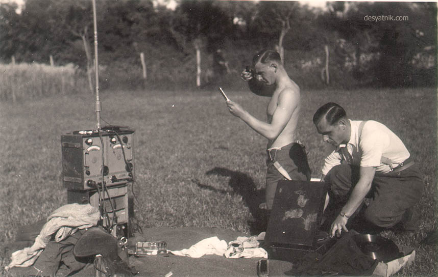
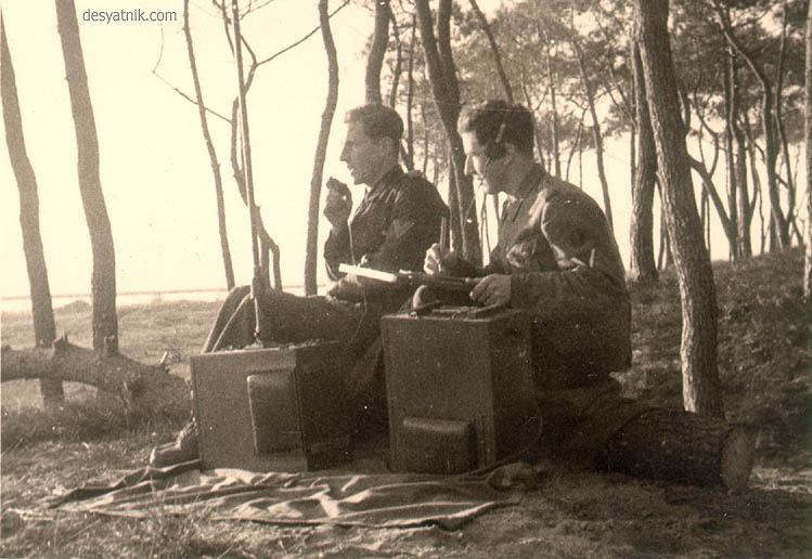
Reference Pictures


Radio Reference Pages
Radio Images -
http://fykse.dnsalias.com/bilder/tornfud2/
Radio Images -
http://www.desyatnik.com/photos/torn_fu_d2.php
Radio Images -
http://www.fieldgear.org/tornfud2.htm
Radio Images -
http://716heer.org/html/torn_fu__d_2.html
Radio Images -
http://www.laud.no/ww2/tornfud2/index.htm
Electrical Diagram for the Torn.Fu.d2 radio -
http://www.radista.info/radio_vhf/Torn_Fu_d2_shema.gif
Electrical Diagram for
German radio -
http://home.online.no/~perchri/torn_fug/tegn4.jpg
Electrical Diagram for
German radio -
http://home.online.no/~perchri/torn_fug/tegn1.jpg
Electrical Diagram for
German radio -
http://home.online.no/~perchri/torn_fug/tegn2.jpg
Electrical Diagram for
German radio -
http://home.online.no/~perchri/torn_fug/tegn3.jpg
Radio Manuals and schematic diagrams -
http://www.radista.info/en_download.html#MANUALS
Radio Images &
schematic diagram -
http://www.rkk-museum.ru/vitr_all/exhibits/308_e.shtml
Battery Label Images -
http://onesixthnet.yuku.com/topic/11767
Model Kit Review -
http://www.modelingmadness.com/scotts/misc/military/previews/dragon/75015.htm
Model Kit Review -
http://www.aeroscale.co.uk/modules.php?op=modload&name=Reviews&file=index&req=showcontent&id=4598
A very good forum
post by Sgt Shultz II I am using for reference here -
Radio Fix
Another very good
radio alteration was done by Actionman -
Radio Changes
This section is continued on
Page Two
Many thanks to David (Actionman)
for the help with the battery labels.
Many thanks to (Seeing
the Unseeable) for originally making the battery labels
Many thanks to
(Sgt
Shultz II) for all his help with how he detailed his radio
sets.
Many thanks to David and Colonel Blimp for pointing me to a UK source for the lenses for the radio.


